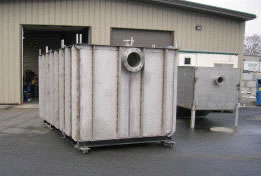
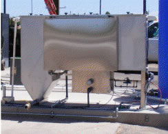
Flow Process Design

When oil is mixed with water (not emulsified), the oil initially exists in the form of droplets of various sizes. In an oil water separator, the oil/water mix enters one end and flows toward the other slowly. If the droplet is large enough and the flow down the tank is slow enough (laminar), the droplet will separate before the end of the tank is reached. The most common oil water separator design uses parallel corrugated plates that cause the oil droplets to increase in size and rise to the surface of the water.

It is very important that the flow through the oil water separator is laminar. To obtain this laminar flow, a cross-fluted design with an internal structure of interconnecting channels between adjacent plates can be used. This design and increased surface area increases the efficiency of the oil water separation. Since Stokes’ Law calculations are based on a flow of zero velocity, a Reynold’s number of less than 500 will ensure optimum separation. Flow through the oil water separator follows these main steps:
- The oil/water/sludge mixture enters the oil water separator
- The heavier sludge and particulates fall out of the fluid and are captured in the sludge hopper
- The oil and water mixture with lighter particulates travels up the inclined plates
- The inclined plates start to separate the mixture. Some oil rises to the top of the separator and the particulates slide down to the sludge hopper.
- The remaining oil and water mixture then moves through the coalescing media packs where the majority of the smaller oil particles attach to the media and coalesce with retained droplets to form larger oil droplets.
- These larger oil droplets become so buoyant that they release from the media and rise to the top of the separator.
- As the oil volume in the separator reaches a certain level, the oil is drained or pumped to an oil storage tank.
- The clean water continues over the weir to the clean water chamber where it goes through a final polishing pack and out to the sewer.